In custom spirits packaging procurement, the single largest cause of tooling delays, budget overruns, and unexpected mold modifications is an incomplete design brief. Industrial designers and creative agencies frequently deliver stunning 3D concept renderings that overlook fundamental glass container forming physics, automatic filling line clearances, and standard capping tolerances. When an unengineered rendering is submitted directly for mold fabrication, manufacturers must either guess critical technical parameters or halt the project for extensive revisions.
A production-grade custom glass bottle design brief is not merely a styling wish list; it is a binding technical roadmap between your brand and the glass factory. By defining essential mechanical parameters, brimful capacity margins, neck finish standards, and decoration keep-out zones upfront, spirits brands can secure accurate tooling quotes, shorten sampling lead times by 2 to 4 weeks, and eliminate costly engineering change orders (ECOs) during pilot runs.
Below is the definitive 18-point technical checklist required by glass packaging engineers before initiating 2D engineering drawings, 3D mold tooling models, and pilot sampling.
Category A: Commercial Profile & Target Operational Scope (Details 1–4)
Before opening CAD software, the engineering team must understand the commercial context of the spirit container. Operational parameters dictate container wall thickness, glass grade selection, and mass-production line allocation.
01. Spirit Type and Alcohol by Volume (ABV)
Specify whether the liquid is a standard distilled spirit (40% ABV vodka, gin, or whiskey), a high-proof cask strength spirit (55%–65% ABV), a high-sugar liqueur, or an acidic RTD cocktail. Liquid density, viscosity, and thermal expansion coefficients directly affect required headspace calculations and internal bore sealing materials.
02. Nominal Fill Volume and Target Export Jurisdictions
Clarify your target retail regions. The United States market operates primarily on 750ml, 375ml, and 1.75L standards under TTB net content regulations, whereas the European Union and most international markets mandate 700ml or 500ml under EU Directive 2007/45/EC. Specifying destination markets determines whether your project requires a single regional mold or a dual-cavity modular tooling strategy.
03. Retail Price Tier and Target Bottle Net Weight
State your desired bottle weight range. Premium and super-premium spirits typically target a container weight between 650g and 950g for a 750ml bottle to achieve a substantial hand feel and heavy base profile. High-volume commercial spirits aim for lightweighting (400g–550g) to reduce raw material costs and ocean freight container shipping expenses.
04. Projected Annual Volume and Initial Run Size
Estimated run sizes dictate mold tooling configuration. An initial pilot run of 20,000 units requires a single-gob or limited-section mold set, whereas an annual demand exceeding 200,000 units warrants multi-section, double-gob Individual Section (IS) machine tooling designed for high-speed continuous manufacturing.
Category B: Dimensional Geometry & Container Forming Limits (Details 5–9)
Glass forming in cast iron molds requires strict adherence to fluid dynamics and thermal contraction principles. The following five parameters establish the mechanical boundary conditions of your bottle.

Dimensional geometry verification: Defining body diameter, overall height, and base proportions prevents filling line conveyor jams.
05. Maximum Height, Body Diameter, and Conveyor Footprint
State the hard physical limits of your bottling facility. Bottles exceeding standard conveyor guide rail widths (e.g., >95mm diameter) or exceeding retail shelf height clearances (e.g., >330mm total height) can cause stability issues on high-speed depalletizers and retail display rejections.
06. Brimful Capacity and Headspace Margin
Nominal volume (e.g., 750ml) is measured to a specific fill height (fill point below the top rim, typically 45mm to 65mm). Your brief must specify required brimful capacity—typically 3% to 5% above nominal volume—to provide sufficient gas expansion space during ocean shipping and temperature swings from 10°C to 45°C.
07. Glass Distribution and Heavy Base Push-Up Thickness
If your aesthetic requires a thick cosmetic base (sham thickness of 12mm to 25mm), note this explicitly. Thick-base designs require blow-and-blow or specialized press-and-blow forming cycles with extended cooling blow schedules to prevent internal glass thermal stress and vacuum shrinkage bubbles.
08. Draft Angles and Corner Radius Minimums
Molten glass contracts as it cools within the mold. Rectangular, square, or fluted bottles require draft angles (typically 0.5° to 1.5° on vertical sidewalls) and minimum corner radii (R ≥ 3mm to 5mm). Sharp 90-degree internal corners create severe stress concentration zones that fail under standard thermal shock tests (ASTM C149).
09. Label Panel Geometry and Recessed Protection Profiles
Define whether the bottle body has a single-curved cylinder, compound multi-curved surface, or flat panel for pressure-sensitive labels (PSL). For high-speed lines, incorporate a recessed label panel (0.3mm–0.5mm indent) with top and bottom bumper rails (contact points) to prevent label scuffing during bulk carton transport.
Category C: Neck Finish & Closure Engineering Interface (Details 10–12)
A custom spirit bottle is only as secure as its closure seal. Over 60% of liquid leakage complaints originate from neck finish mismatches between glass mold drawings and closure supplier tooling specifications.

Neck finish integrity: Defining bar top bore dimensions and entrance chamfers ensures leak-free synthetic cork seating.
10. Neck Finish Classification
State the standard neck finish family: Bar Top (cork stopper), Continuous Thread (GPI/GCMI screw finish such as GPI 28-400 or GPI 33-400), Roll-On Pilfer-Proof (ROPP aluminum finish), or specialized glass/synthetic stoppers (Vinolok). Never list “standard neck” without an established engineering standard code.
11. Internal Bore Diameter and Sealing Depth Tolerances
For bar top closures, specify the nominal bore diameter measured at both 5mm and 20mm below the rim (e.g., 18.5mm ± 0.5mm, or 21.5mm ± 0.5mm). Include requirements for internal bore entrance lead-in chamfers (0.5mm–1.0mm radius) to prevent cork shearing during automated insertion.
12. Tamper-Evident Capsule and Neck Band Compatibility
If your closure includes a PVC heat-shrink sleeve, polylaminate capsule, or wax dip, specify the outer neck collar profile (corker bead/bulge) and neck taper. An improper collar profile causes capsule wrinkling or premature slippage during packaging.
Category D: Decoration, Embossing & Surface Treatment Boundaries (Details 13–15)
Secondary processing transforms a bare glass bottle into a distinctive brand asset. However, decorating processes require specific clearances from mold parting lines and thermal lehr handling equipment.
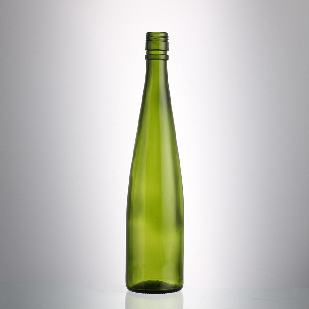
Secondary decoration zones: Marking silkscreen printable areas and parting line clearances prevents ink smudging and registration errors.
13. Target Surface Finish and Decoration Technologies
State all planned secondary processes: acid-etched full frosting, gradient spray coating, multi-color ceramic silkscreen printing (ACL), high-fire decal application, hot stamping foil, or electroplating. This allows the mold shop to adjust glass surface roughness and thermal tolerance windows.
14. Printable Area and Mold Seam Keep-Out Zones
Silkscreen print screens cannot bridge vertical mold parting lines (seams) cleanly without risking ink pooling or jagged edges. Your brief must specify printable panel heights and maintain a minimum 3mm to 5mm keep-out margin on either side of mold seams unless high-temperature wrap-around decals are utilized.
15. Glass Embossing/Debossing Depth and Draft Radii
For brand logos or text molded directly into the glass, define relief depth (recommended 0.5mm to 1.2mm for embossing; 0.4mm to 0.8mm for debossing). All embossed stroke widths must exceed 0.8mm, with 15° to 30° draft angles on character sidewalls to prevent glass sticking to mold cavities during ejection.
Category E: Packaging, Quality Standards & Digital Deliverables (Details 16–18)
The final section defines how the finished containers will be packed, inspected, and handed over in CAD engineering formats.
16. Secondary Packaging and Transport Configuration
Specify delivery format: bulk palletized with tiered layer pads and shrink hood (for automated distillery depalletizers), or partitioned corrugated reshipper cartons (6-pack or 12-pack custom printed boxes). Reshippers protect decorated bottles from abrasion and allow direct repacking after filling.
17. Quality Acceptance Thresholds and AQL Sampling Framework
Establish contractual acceptance limits using ISO 2859-1 (AQL). Define agreed thresholds: Critical Defects (AQL 0.0, e.g., birdswings, open cracks, broken rims), Major Functional Defects (AQL 1.0–1.5, e.g., neck bore out-of-round, thread deformation), and Minor Cosmetic Defects (AQL 2.5–4.0, e.g., minor air seeds, faint mold wash marks).
18. CAD File Formats and 2D Engineering Dimension Deliverables
Provide design assets in neutral 3D CAD formats (.STP / .STEP or .IGES) alongside dimensional 2D engineering drawings (.PDF / .DWG) that clearly indicate critical baseline datum planes, center-of-gravity targets, and required volume calibration points.
Comparison Matrix: Concept Rendering vs. Production-Ready Technical Brief
The table below illustrates how common design ambiguities in creative renderings translate into engineering risks, and how a rigorous brief resolves them.
| Design Parameter | Typical Creative Concept File (Incomplete) | Production-Ready Technical Brief (Engineered) |
|---|---|---|
| Neck Finish & Bore | 3D mesh neck model without standard thread or bore tolerance specs. | Standard code (e.g., Bar Top 21.5mm ± 0.5mm bore, 25mm depth) matched to stopper SKU. |
| Capacity & Headspace | Nominal 750ml stated, but total internal volume equals exactly 750ml (zero expansion). | Nominal 750ml @ 55mm fill point; Brimful capacity specified at 785ml ± 5ml (4.6% margin). |
| Corner Geometry | Sharp 90° edges and flat vertical walls with 0° draft angle. | R ≥ 4.0mm corner fillets and 1.0° draft angle for smooth mold release and strength. |
| Embossed Lettering | Thin serif typography (0.3mm stroke) extruded 2.0mm straight out. | San-serif or robust serif (stroke ≥ 0.9mm), 0.8mm relief depth, 20° draft angle sidewalls. |
| Secondary Packaging | Omitted (“standard factory packing”). | Defined as 12-bottle partitioned double-wall reshipper cartons on heat-treated ISPM-15 pallets. |
Strategic Next Steps: Submitting Your Brief for DFM Engineering Review
Before releasing final purchase orders for custom tooling, execute a 5-step internal verification of your design package:
- 1. Cross-Check Filling Line Envelope: Validate total bottle height and maximum body diameter against your co-packer’s conveyor starwheels and labeling machines.
- 2. Perform Closure Fitment Pre-Validation: Obtain technical drawings from your cork/cap supplier and overlay them onto the bottle neck finish drawing.
- 3. Verify Brimful Headspace: Ensure the calculated expansion volume accommodates liquid thermal expansion for high-proof spirits.
- 4. Review Mold Parting Lines: Check that critical branding elements and silkscreen art clear mold seams by at least 3mm.
- 5. Request a Formal DFM Report: Submit your 18-point brief to the glass engineering team for a Design for Manufacturability (DFM) assessment prior to cutting steel.
To begin custom bottle development or evaluate your design concept with our container engineering team, submit your CAD assets and technical specifications through our Request a Quote portal for a comprehensive DFM feasibility and tooling analysis.
Frequently Asked Questions (FAQ)
Can a glass manufacturer start mold production from an image rendering alone?
No. A 3D graphic rendering (such as Maya, Blender, or Cinema 4D polygon meshes) lacks dimensional wall thicknesses, internal volume calculations, and draft angles. The manufacturer’s engineering team must convert the concept into parametric NURBS CAD geometry (.STEP / .IGES) and produce a fully dimensioned 2D engineering drawing before any CNC mold machining can begin.
Why does the factory need to know my bottling line speed?
Bottling line speed determines required bottle stability and glass distribution. High-speed commercial lines running at 120+ bottles per minute require low centers of gravity, broad contact bumper rails, and uniform round bodies to prevent tipping and line jams. Craft distilleries with semi-automated lines (20–40 bpm) can accommodate complex asymmetrical shapes and heavier base profiles.
Who is technically responsible if the synthetic cork leaks after mass production?
Responsibility depends on drawing alignment. If the glass manufacturer produces bottles within the signed 2D engineering bore tolerance (e.g., 18.5mm ± 0.5mm), but the chosen stopper was sized incorrectly for that bore range, responsibility rests with the buyer. If the bottle bore exceeds the agreed tolerance envelope, the glass manufacturer is liable. This makes cross-supplier drawing validation in the design brief essential.
What is the minimum draft angle required for rectangular or square spirits bottles?
Rectangular and square containers generally require a minimum draft angle of 0.5° to 1.5° on all vertical side panels. Flat panels with 0° draft tend to drag and scuff against the cast iron mold cavity during opening, leading to surface chill checks, shear marks, and elevated rejection rates.
Post time: Oct-16-2026